I have had some of these electronic components for a long time, but I never got around to trying them. I want to create an IMU (Inertial Measurement Unit) without any particular need. There are probably already ready-made, simple, and better solutions, so this is just for fun. The sensor is the InvenSense MPU-6050 Six-Axis Gyro + Accelerometer. This sensor is not recommended for use in new projects as it has been replaced by a newer generation. The chip also includes a Digital Motion Processor™ (DMP™), which I do not wish to use, even though I am confident the result would be better.
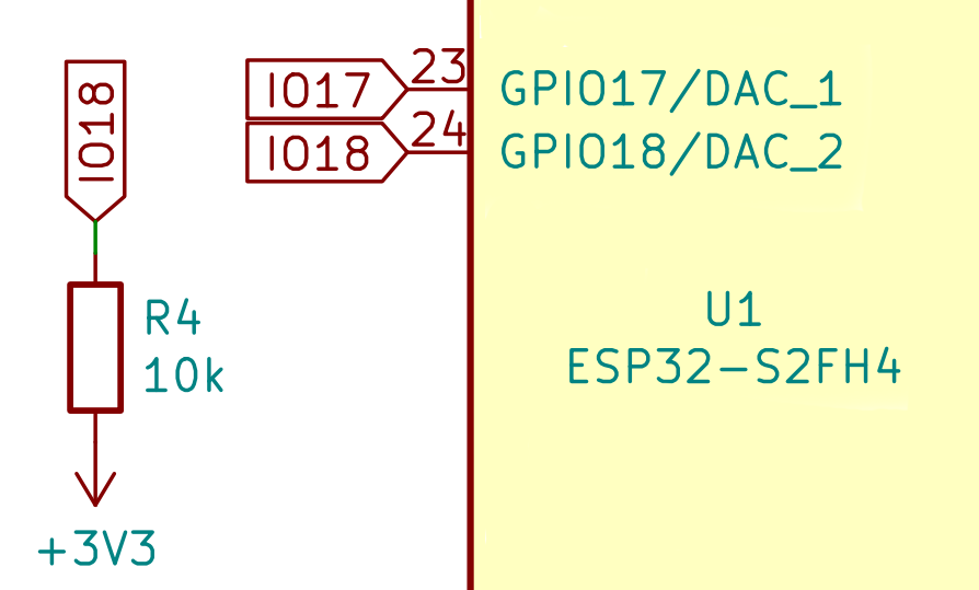
Here is the block diagram and test setup, but in this case, the compass is missing.

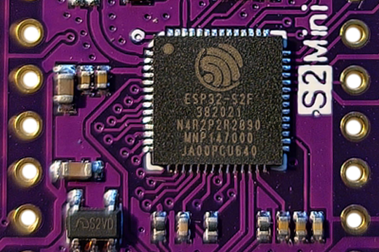
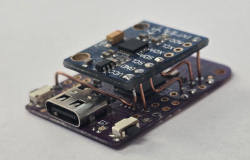
And here is roughly what the test platform looks like: Wemos S2 Mini ESP32-S2 and GY-521 (MPU6050)
To start, I’ll at least try to read the RAW data from the sensor. Datasheet for MPU-6050 and register map.
import micropython, esp
from machine import Pin, SoftI2C

key = Pin(0, Pin.IN, Pin.PULL_UP)  # reset button
led = Pin(15, Pin.OUT)  # on-board LED

# MPU registers
ADDRESS = 0x68
ACCEL_RANGE_2G = 0x00
GYRO_RANGE_250DEG = 0x00
PWR_MGMT_1 = 0x6B
PWR_MGMT_2 = 0x6C
ACCEL_XOUT0 = 0x3B
CONFIG = 0x1A
GYRO_CONFIG = 0x1B
ACCEL_CONFIG = 0x1C

i2c = SoftI2C(scl=Pin(36), sda=Pin(38), freq=400000)
i2c.start()
i2c.writeto(ADDRESS, bytearray([PWR_MGMT_1, 0x00]))
i2c.writeto(ADDRESS, bytearray([ACCEL_CONFIG, ACCEL_RANGE_2G]))
i2c.writeto(ADDRESS, bytearray([GYRO_CONFIG, GYRO_RANGE_250DEG]))
i2c.writeto(ADDRESS, bytearray([CONFIG, 0x00]))
i2c.stop()

loop = True
led.value(1)

while loop:
    i2c.start()
    raw = i2c.readfrom_mem(ADDRESS, ACCEL_XOUT0, 14)
    i2c.stop()

    print(raw)

    if key.value() == 0:
        loop = False

led.value(0)
The result should look something like this. It is not very useful, but at least we know that communication with the sensor works.
b'\xcb\\\x02\x84\xd30\xf8`\xf1\xb5\xfc\xf7\xee\xf6'
b'\xd2\xb4\x01\x9c\xd5T\xf8p\xf0\xd9\xfc\xee\xec_'
b'\xce\xd0\x00\xec\xd3\xc0\xf8\x80\xf0\x9f\xf8\xb6\xea\x8b'
b'\xcdx\xff\\\xd9\x00\xf8\x90\xefH\xfb\x0e\xea '
b'\xcfX\x00\x88\xd5p\xf8`\xef\x8d\xf6|\xe9\x85'
b'\xcet\x00\x08\xd6|\xf8p\xef\xb2\xf3\xbf\xe9\xde'
b'\xd2T\xfe\xc0\xd6P\xf8\x80\xef\xe7\xf3e\xeb\x00'
b'\xd5\xcc\xff\xe8\xd6\xac\xf8\x90\xef\xae\xf6\xa3\xeb\x8b'
b'\xd4\xa4\x00\xd8\xd5\x84\xf8\xa0\xef]\xfa\\\xeb_'
b'\xd6L\x00l\xd6\x00\xf8\x90\xef2\xfek\xeb\\'
b'\xd3\\\x01\x84\xd3,\xf8\x80\xefO\xfe\xaf\xe9\x83'
b'\xd6<\x01\xd8\xd6h\xf8\x90\xed\x73\x05\xcf\xe7\xd9'
Everything together, along with future posts, can be found here.
Now, let’s try to make the MPU6050 generate an interrupt and read sensor data within the interrupt routine. I have removed the print(raw) to measure timing and sampling stability.
INT_ENABLE = 0x38

interrupt_pin = Pin(40, Pin.IN, Pin.PULL_UP)  # Connect INT pin from MPU6050 to GPIO40

# Variable to track interrupt handling
handle_interrupts = True

# Interrupt handler
def handle_interrupt(pin):
    global handle_interrupts
    if handle_interrupts:
        i2c.start()
        raw = i2c.readfrom_mem(ADDRESS, ACCEL_XOUT0, 14)
        i2c.stop()
        # do something

# Attach interrupt
interrupt_pin.irq(trigger=Pin.IRQ_FALLING, handler=handle_interrupt)

while True:
    if key.value() == 0:
        handle_interrupts = False  # Stop handling interrupts
        interrupt_pin.irq(handler=None)  # Detach the interrupt handler
        break
I will attempt to make the ESP32 act as a Wi-Fi access point and broadcast RAW sensor data, then try to use that data to determine orientation on the receiving computer.